The powder particles are compacted to form
a coherent shape with sufficient strength for subsequent handling.
If necessary, this shaped, unsintered mass of powder (known
as a green body) can be machined economically before firing,
since corresponding steps are much more expensive after sintering.
When applying the various forming processes, care must be
taken to avoid significant density gradients and textures
in the green body, since these can be amplified during sintering,
leading to distortions and internal mechanical stresses. The
choice of a suitable forming process is usually determined
by economic factors (efficient manufacturing).
Methods of shaping ceramic parts can be divided into the
following basic types:
is used to manufacture mass-produced precision products.
Non-clumping granulates are compressed in steel dies designed
appropriately for the part to be manufactured. The high cost
for the dies (sometimes made of carbide) can only usually
be justified for large runs.
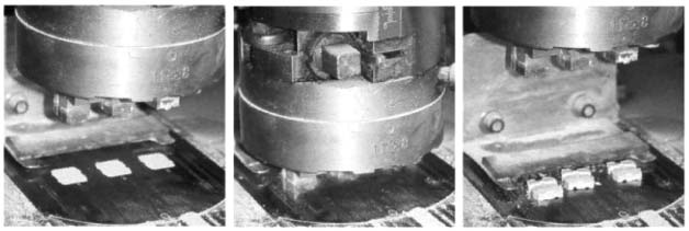
Figure 53: Dry pressing
Figure 54: Single axis dry pressing, single
and double ended, with regions of different compression
(grey levels)
Dry pressing is the most economic process
for large production runs, and is suitable for both simple
and complex geometries. Depressions and holes are normally
only designed in the pressing direction.
Depending on the design of the dry pressing machine, components
ranging in size from tiles down to match heads can be manufactured.
Small discs or plates can be pressed with thicknesses of
around 0.8 or 1.0 mm. The tape casting process is more suitable
for even thinner, flatter components. It is still possible
to manufacture fine ridges or similar structures on the
component if the granulate being pressed can effectively
fill hollows in the pressing tool, and provided it is possible
to create the necessary tool.
Isostatic pressing
is suitable for the manufacture of uniformly
compressed blanks and large parts that are appropriate for
machining in the green state. Simple rubber moulds determine
the initial form.
Figure 55: Isostatic pressing with regions
of different compression (grey levels)
This type of forming is well-suited to the manufacture of
exacting prototypes and small series, but for some products
can also be fully automated (spark plugs, grinding balls,
small pistons, welding nozzles).
Wet pressing / moist pressing
allows the manufacture of parts with complex geometries
such as screw threads, side holes, recesses and undercuts.
The unfired material used for this purpose usually has moisture
levels in the range of 10 to 15%. Compressing with a single
axis makes these materials able to flow freely, so that
relatively even compression can be achieved.
The disadvantage of this, however, is that wet pressing
materials can accept only low compressive strains. This
also means that the degree of compression is limited. It
depends heavily on the moisture content of the unfired material,
and is lower than in the case of dry pressed parts. In some
circumstances, moreover, it is necessary to dry the pressed
parts before sintering. Mean tolerances in accordance with
DIN 40 680-1 are based on this.
Extrusion
is carried out using piston extruders or vacuum screw presses.
The homogenised mass of material is pressed through a nozzle,
so forming endless billets. Optimum compression of the material
is important. Extrusion is particularly suitable for manufacturing
rotationally symmetric parts such as axles or pipes. Complex
profiles can also be made with the aid of appropriate nozzle
design. The lengths of the billets to be manufactured depend
to a large extent on the tendency of the material being
processed to warp.
Figure 56: Extrusion
Injection moulding
is principally suited to the mass production of complex
products. It is limited by relatively high die costs and
the complex burnout of organic additives. The conveying
capacity ("shot weight") of large injection moulding
machines is typically up to about 70 g. Generally, the part
should be designed so that thicknesses are as consistent
as possible, having an upper limit of approx. 12 mm.
Slip casting
is a simple method for the manufacture of prototypes, parts
with complex geometries and relatively large items. It can
be used to manufacture both thin-walled and solid objects.
Ceramic slip casting involves a stable suspension, referred
to as the slip, being poured into a porous, absorbent plaster
mould. Extraction of the suspending liquid causes a layer
of particles to develop on the mould wall. This layer develops,
in solid casting, to create the fully moulded body. In the
case of hollow casting, the superfluous slip is poured out
once the desired wall thickness has been achieved.
Tape casting
Here, a ceramic slip containing various organic additives
is poured onto an endless steel strip carried by rollers.
The slip flows continuously from a reservoir through an
adjustable slot onto the strip. Hot air is blown over the
strip in the opposite direction to dry it, so that at the
end of the strip, thanks to the organic additives, a flexible
tape of green ceramic is obtained. This can either be wound
up and stored for further processing at a later time, or
maybe processed immediately through cutting, punching, stamping
or other similar methods. Tape casting is typically used
to manufacture ceramic parts with thickness ranging from
0.25 to 1.0 mm. The formed products are suited for the manufacture
of substrates, housings, capacitors and multi-layer transducers.
Figure 57: Tape casting
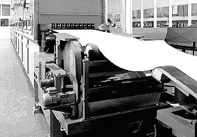
Figure 58: Tape casting machine
The choice
of the forming process to be used in any particular case
depends, from a technical point of view, on the geometry
and size of the part and the needs of the application. The
piece count, raw material consumption and process costs
determine the most economic choice.
Further extensions to the forming processes initially introduced
here are possible.
Table 3: Summary of ceramic
forming processes
Table 4: Advantages and disadvantages of common
forming processes