10.5.1.1 3-point
Bending Test
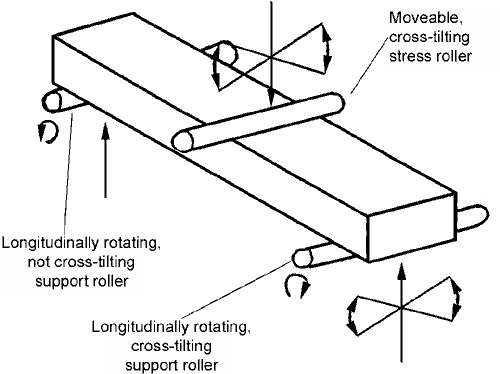
The test jig consists of two parallel supports
for the sample and a single loading pin in the middle, between
the supports, where the force is introduced. The support pins
must be mounted in such a way that they can rotate freely
on their axes in order to minimise the influence of friction
on the measurement. One of the supports must also be able
to rotate about an axis perpendicular to this and parallel
to the axes of the sample so that the test piece can align
itself when under stress. The loading pin must also possess
similar rotational axes in order to ensure the uniform application
of force on the test piece. The diameter of the support and
loading pins and the distance between the centres of the supports
(the loading span) can be taken from Table 33. The surface
must be polished and free from burrs. The force is introduced
perpendicularly to the test piece plane and/or the support
plane. A typical set-up for such an instrument is shown in
figure 212.

Figure 212: Schematic illustration of the
3-point bending test
|

